 button to have the program generate the desired
shape definition for you.
button to have the program generate the desired
shape definition for you.There button to have the program generate the desired
shape definition for you.
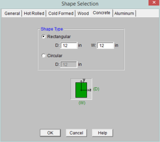
Rectangular sections are defined using a parametric shape code since a rectangular shape may be any depth or width. The code is CRECT'depth'X'width', where 'depth' and 'width' are the values in the current dimension units. For example, if you wanted a beam that was 18" deep and 12" wide, you would enter "CRECT18X12". Note that the dimensions can also be decimal values like "18.25".
Circular/Round sections are also defined using a parametric shape code since a round shape may have any diameter. The code is CRND'diameter', where 'diameter' is the value in the current dimension units. For example, if you wanted a column that was 14" in diameter, you would enter "CRND14". Note that the dimension can also be a decimal value like "14.5".
![]() button on the RISA Toolbar
button on the RISA Toolbar
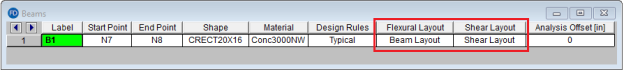
These reinforcement layouts may be assigned to beam
For additional advice on this topic, please see the RISA Tips & Tricks webpage at risa.com/post/support. Type in Search keywords: Custom Rebar Layouts.
Since beams are only designed for uniaxial bending, the only requirements for the beam layouts are that you specify the depth at which the bars are located and the size & number of the bars that are present at that depth. You can specify the depth with respect to the top surface of the beam or the bottom surface.
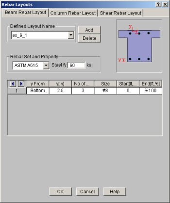
The Start and End locations dictate the location along the length of the beam where these bars will be present. You can use these entries to specify partial length bars that will only be present in locations with a higher moment demand. If the bar should be present for the entire length of the beam, the start location should be '0' and the end location should be '%100' as shown in the dialog above.
Note
 can be used to advance from cell to cell.
 Since columns are designed for biaxial bending, they require more information about the location and arrangement of the bars.
Normally, column bars are arranged in layers. One 'Top' and one 'Bottom' horizontal layer must always be defined, each containing at least two bars. These layers, as well as any additional horizontal layers, will be specified by entering a y1 value to specify the depth from the top or bottom fiber to the centerline of the reinforcing steel. The number and size of the bars must then be entered. The z1 and z2 values dictate where the first and last bar in that layer are located. Additional bars in that layer will be placed so that they are evenly spaced in that layer.
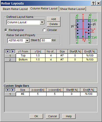
Vertical layers can be specified by entering a y1 value specifying the depth from the right or left most fiber to the centerline of the reinforcing steel. The number and size of the bars must then be entered. The z1 and z2 values are ignored for vertical layers because the bars will be assumed to be evenly spaced between the required top and bottom layers referred to previously. If this is not desired, then the side bars should be entered individually as custom single bars.
Custom single bars are specified by their y and z coordinates measured from the local y and z-axis respectively. A positive y coordinate would place the bar closer to the top fiber and a negative y coordinate would place the bar closer to the bottom fiber. Similarly, a positive z coordinate would place the bar closer to the right side and a negative z coordinate would place the bar closer to the left side.
The Start and End locations dictate the location along the length of the member where these bars will be present. You can use these entries to specify partial length bars that will only be present in locations with a higher moment demand. If the bar should be present for the entire length of the member, the start location should be '0' and the end location should be '%100' as shown in the dialog above.
For circular columns, you may specify equally spaced concentric rings of bars at given depths, z1, measured from the exterior fiber of the column. You may also specify custom single bars.
Custom single bars are specified by their y and z coordinates measured from the local y and z axis respectively. A positive y coordinate would place the bar closer to the top fiber and a negative y coordinate would place the bar closer to the bottom fiber. Similarly, a positive z coordinate would place the bar closer to the right side and a negative z coordinate would place the bar closer to the left side.
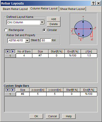
The Start and End locations dictate the location along the length of the member where these bars will be present. You can use these entries to specify partial length bars that will only be present in locations with a higher moment demand. If the bar should be present for the entire length of the member, the start location should be '0' and the end location should be '%100' as shown in the dialog above.
Note
can be used to advance from cell to cell. These rebar layouts
The Start and End
locations dictate the location along the length of the
Note
can be used to advance from cell to cell.